
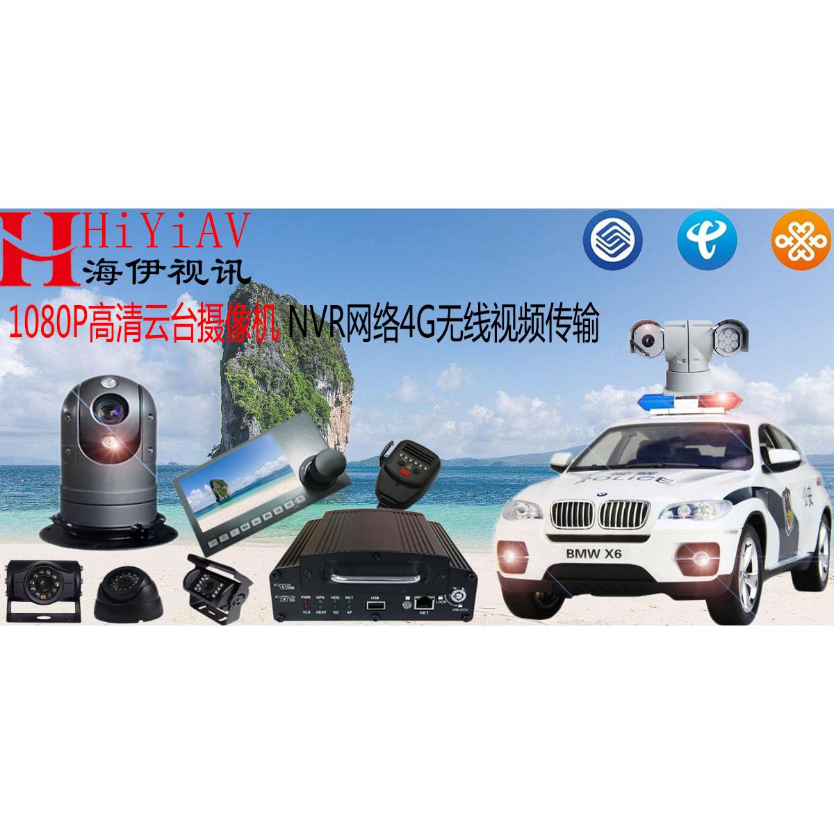
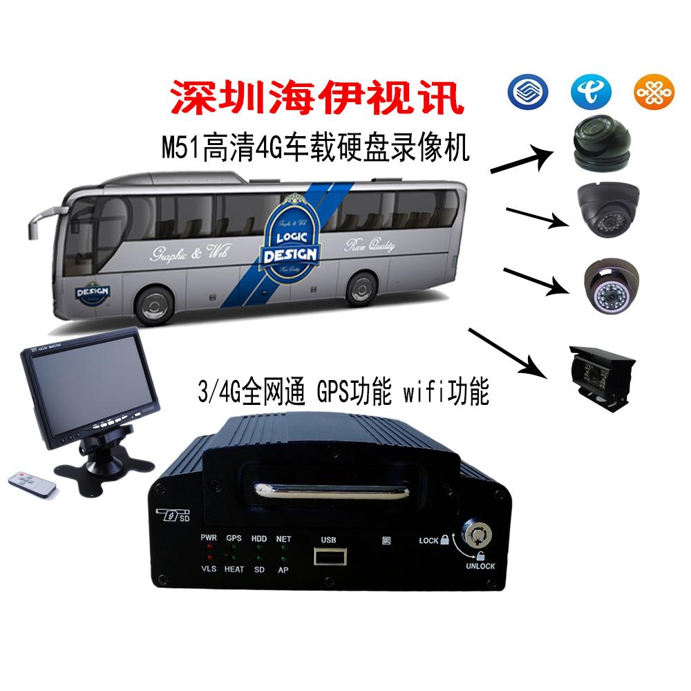
M51It is a high performance and extensible device specially developed for vehicle video surveillance and remote surveillance. It combines high-speed processor with embedded operating system.ITThe most advanced in the fieldH.264video compression/Decompression technology.DAE2000Support4Road video is recorded at the same time.DAE2000Realizable4road720p /960P(AHDSimulated HD,1road1080P、D1、CIFOptional Video Function in Various Formats,BeltGPS/BDGPSLocation, vehicle driving information record and wireless data upload, together with central software, can realize central monitoring, remote management and playback analysis based on central database. The product has the characteristics of simple appearance, super anti-vibration, flexible and convenient installation, powerful function and high reliability.
Detailed features are as follows:
Industrial design, vehicle-mounted special interface to ensure reliable and stable operation of products in complex environments;
The latest audio and video compression technology;
Support4Road audio and video storage;
Professional and stable special file system;
Extensible3G、4G、WIFI、GPS/BDGPSFunction modules;
Support local and remote platform control;
Support1Five hard disks and1ZhangSDCard;
HavePTTCluster intercom function;
Supporting Hard Disk BoxUSB3.0Interface to guide data;
SupportUSBInterface data backup;
External supportUPSPower supply continuity;
Quick start-up;
Supporting mobile terminal monitoring software such as Apple and Android.
Support808/809Ministry Standard Platform Protocol
The product is suitable for video surveillance and remote surveillance of all motor vehicles. chart1It is the system scheme diagram of product application.DAE2000The general application process is as follows:
1. When the vehicle runs on the route:
The product videotapes the scene or road condition in the vehicle.
Record vehicle status and other traffic information;
2. When the vehicle returns to the terminal:
adoptUCopy or replace the storage device to download the video for a specified period of time.
Through playback analysis software to achieve the analysis of downloaded videos.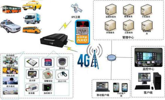
It integrates a set of hardware video encoding chips to complete the system's encoding, video storage, decoding and playback functions. The video recording system consists of the following components:
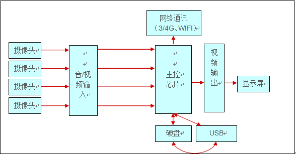
Block diagram of monitoring system
The workflow is as follows:
Video and audio recording:
Video and audio are input through the camera, then compressed and stored on the main chip and previewed the output.
Local and remote playback:
1.Local playback
The main control chip obtains video files from storage devices.
Decode and play, generate audio and video analog signals;
2. Remote playback
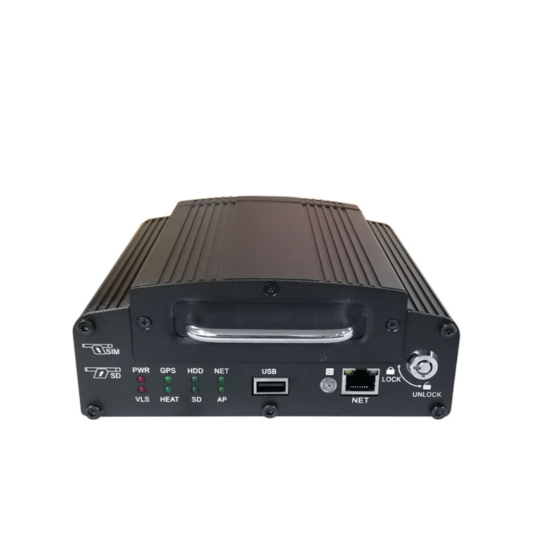
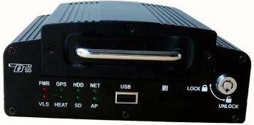
Front panel definition
The front panel is shown in the following figure:
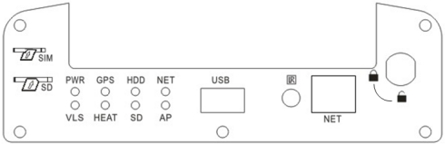
【PWR】 Power input status indicator.LEDThe lamp is always on to indicate that the power supply of the system is working normally.
【VLS】 Video loss alarm lights.LEDLighting indicates video loss in four-way video input.LEDThe light out indicates that the video input is normal.
【GPS】GPSSignal light.LEDWhen the light is on, the device is positioned successfully.LEDWhen the light goes out, the device fails to locate successfully or the module is not found.
【HEAT】 Hard disk heating indicator.LEDThe light is heating the hard disk.LEDWhen the lamp goes out, the hard disk is not heated.
【HDD】 Hard Disk Working Indicator Lamp.LEDThe lamp always lights up to indicate that the hard disk exists and the lamp flashes to indicate that the video is being recorded.LEDWhen the lamp goes out, it means that there is no hard disk or the equipment is abnormal.
【SD】SDCard work indicator.LEDThe lamp is always on.SDThe card works normally.LEDWhen the light goes out, it means nothing.SDCard orSDThe card is not normal.
【NET】 Working condition indication of communication function. Communication module is always bright, but no communication module is extinct. Flash when there is data transmission.
【AP】APIndicator light. When equipment acts asAPIn the mode, the light is on and flashes when there is data transmission.
【USB】For:UDisk import and export data or upgrade.
【IR】 Remote control input: Used to receive the signal of user remote control.
Back panel definition
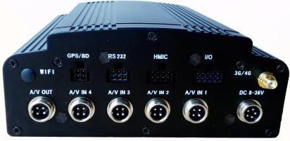
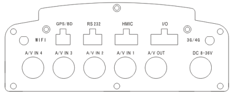
【DC8-36V】 Power supply interface, red wire for on-board power supply cathode; black wire for on-board power supply cathode; yellow wire for on-board power supply cathodeACCThe signal line. When timing or ignition videos need to be set, pick up the vehicleACCLine.
【I/O】 External alarm input and output interface.
【HMIC】 Hand-wheat interface.
【RS232】 Reserve serial interface.
【GPS/BD】 OutsideGPS/BDModule interface.
【3G/4G】3G/4GAntenna interface.
【WIFI】WIFIAntenna interface.
【A/V IN 1-4】 Four-way audio and video input interface.
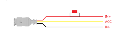
The following figure shows the power cord, one end of which is5PIN Aviation plug, attached to the back panel of the equipmentDCOn the public joint. The red and black wires are connected directly to the battery of the car. The red wire connects the positive pole and the black wire connects the negative pole. Yellow wire is connected with ignition wire, and the main equipment automatically opens after the car key is opened, and automatically closes after the car key is closed. The yellow wire is connected to the gear when the car key opens all the dashboard lights.(That's the gear before the car starts the motor.)。
Be careful:
1) Before connecting, it is necessary to confirm that the battery voltage is at12V—36VIn the meantime, excessive voltage may cause burnout of equipment.
2) After connecting the wires, attention should be paid to the insulation between the power lines to prevent the short circuit of the power lines from burning out the battery.
M51List of Major Functions
| system |
function |
Explain |
| Video Subsystem |
Video channel |
4Road access |
| Resolving power |
Supporting the highest4road720P/960P/1road1080PResolution Video Recording |
|
| Picture quality |
Default Quality4M bps |
|
| OSD |
Various characters can be superimposed, such as date, time, channel.IDWait |
|
| loop record |
Support hard disk circular recording and circular deletion |
|
| Video mode |
Support boot-up video, timing video, alarm video and manual video |
|
| preview |
Supporting single-screen and four-screen Preview |
|
| Disk Overlay |
Support disk auto-coverage |
|
| Playback subsystem |
Video Search |
Support search at any time in a day |
| Support alarm point search and time point search |
||
| playback |
Supporting single-to-four-way synchronous playback |
|
| Supporting Fast Forward, Fast Back, Fast Forward and Fast Back2、4、8、16Double speed |
||
| Call the police |
input |
4Circuit switching quantity,2Road analog alarm input is optional, whether trigger alarm video is optional |
| Alarm Video Support Before Police15Dynamic allocation of seconds and post-police video duration |
||
| Parameter Settings |
Switching Machine |
Delay Switch Support |
| Support key switch and timing switch |