I. Brief Introduction
LS-1 radar is a new type of microwave velocity measurement radar. It uses millimeter wave and digital signal processing technology. It has the characteristics of small size, light weight, easy operation, unique data interface and state control function. It is very suitable for secondary development and technology integration of velocity measurement products.
II. Working Principle
LS-1 Radar Velocimeter is a K-band microwave velocity radar. Its working principle is based on Doppler principle. From the Doppler principle, we know that when a beam encounters a moving object, the returned wave will have a frequency shift, which is proportional to the velocity of the moving object. Using this principle, we transmit a fixed frequency microwave, then measure the frequency of the return signal, measure its frequency shift speed, and then calculate the target speed.
Main functions and technical indicators:
LS-1 is a static test radar. In the process of testing, the radar needs to be fixed on a certain position and then measure the speed of the target. In addition, LS-1 can set the speed limit according to the user's needs, and after setting it, the speed limit can be saved by power off. In the process of testing, when the target or target speed exceeds the speed limit, the system will send out an indication signal.
Technical Indicators
1. Working Voltage: DC12V
2. Working current: less than DC 300mA
3. Speed measurement range: 1 km/h-200 km/h (0.4m/s-27m/s)
4. Test distance: greater than 100m
5. Speed limit range: 2 km/h-180 km/h (0.5 m/s-22m/s)
6. Data Interface Settings: 9600
7. Data transmission format: ASCII code, three data bits plus return line change.
8. Data transmission format: 9600 baud, no check, one start, eight data, one stop bit.
9. Dissipative Power: Test Status: Less than 0.5A
10. Whole machine weight: less than 500 g
11. Transmitting frequency: 24.15 GHz
12. Transmitting power: 5mW
IV. System Composition
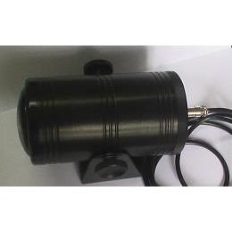
LS-1 radar is mainly composed of mainframe and test components.
Host: Used to complete the speed measurement, the measurement results are sent to 232 interface.
Power cord, data line, control line, instrument box, etc.
In addition to the basic configuration, users can also add options according to requirements, the main options are display unit or palmtop.
Display unit or palmtop is used to detect or set up radar. Settings are done by computer when these selections are not available.
There is a five-core socket behind the radar to connect the power supply and 232 ports.
V. Operating methods
When the system is connected with the control unit, the power supply is turned on and the system enters the working state. At this time, the system begins to measure the speed, and the measured results are sent out through RS-232. When there is a target, the system sends the measured data through RS-232. At the same time, the data test line is set to be high, which means that the target enters the test area. When the test data exceeds the speed limit, the overspeed mark line is set high. The structure of velocity measurement is ASCII code, and the first three represent 100 bits, 10 bits and individual of the target respectively. The end of the data ends with a return line.
If you need to display, you can connect the serial data line to the computer or palmtop control equipment and the large screen connection.
Notes
1. Test angle:
The velocity measured by radar is the velocity of moving object along the direction of radar beam. Therefore, the direction of measurement should be the same as the direction of target motion, and generally should be kept within 10 degrees. The influence of angle can be expressed as follows:
Vr =V*COS(A)
Among them, A is the angle between the moving direction of the target and the radar beam, that is, the angle between the moving direction of the target and the radar pointing. Excessive angle will cause errors.
2. Test equipment should be avoided as much as possible in rain.