I. Preface
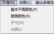
2. Introduction of Software Interface
3. Importing the Documents of Traffic Accident Site Maps
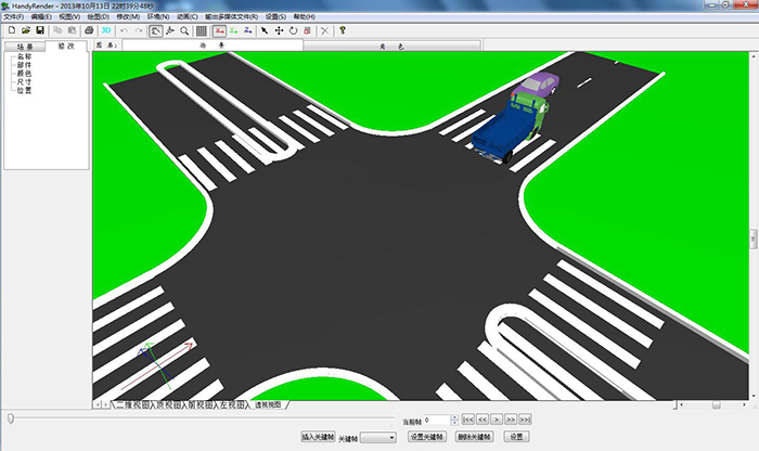
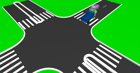
4. Generating 3D effects and viewing them in multiple directions
V. View Tools and Graphics Tools
6. Adding and modifying roles and scenarios
7. Bloodstains, Scatters, Traces
8. Generating Animation
9. Output of Multimedia Files
I. Preface
Traffic accident scene three-dimensional simulation system is a software that uses virtual reality technology to reproduce traffic accidents. It adopts the leading technology in China and has completely independent intellectual property rights. This system is simple to operate and does not depend on the third-party graphics platform. Operators can complete scene, vehicle and character reproduction in 30 minutes after simple training, and generate AVI video files. It can simulate realistically to achieve dynamic effects. The software provides a large number of three-dimensional graphics libraries (including buildings, trees, car models, etc.) and can set various colors of lights. It can select suitable materials for different objects to map, in order to achieve realistic traffic accident scene virtual simulation effect. The software can be used in conjunction with the company's two-dimensional traffic accident scene drawing software to automatically complete the modeling of roads and vehicles, save operation time and improve ease of use. The system is suitable for the research and analysis of the causes of traffic accidents, the analysis and explanation of accident cases, the mediation of traffic accidents disputes, the warning and propaganda of the high-risk groups of traffic accidents (such as schools, driver training schools), etc. It is the main tool and powerful assistant of traffic management workers.
Hardware environment configuration requires more than 1GB of memory in Microsoft Windows XP operating system and more than 20GB of hard disk 1024*768 resolution color display 128MB or more OpenGL graphics acceleration card.
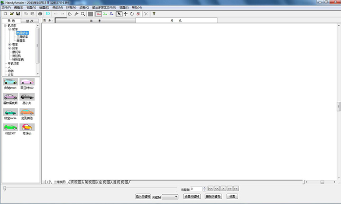
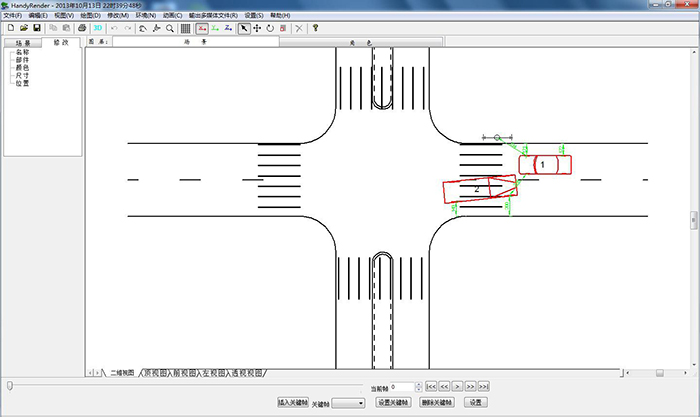
2. Introduction of Software Interface
Double-click the icon of the three-dimensional traffic accident simulation system on the desktop to open the software.
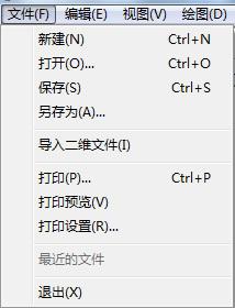


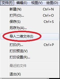
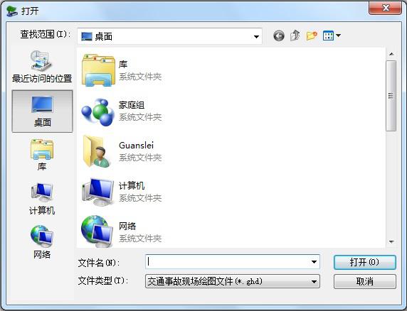
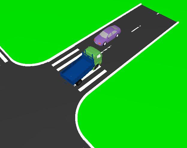
Select the pre-saved traffic accident scene map file and click "Open".
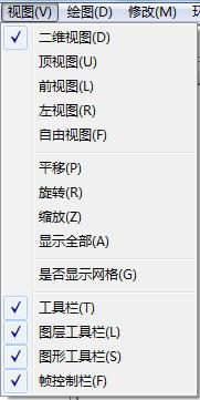
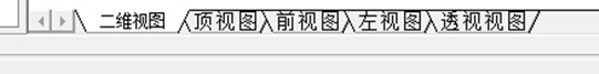
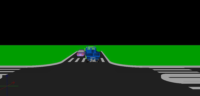
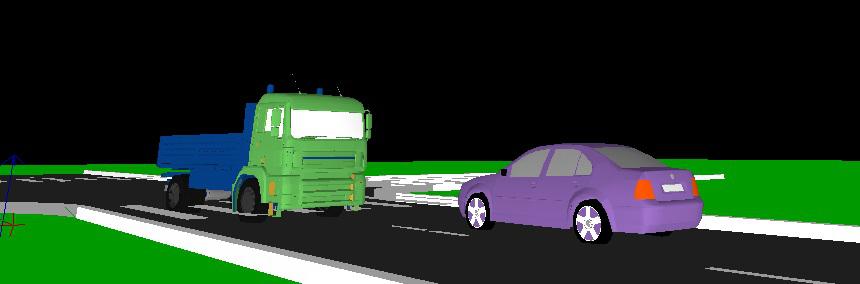
 (3) Front view
(3) Scaling
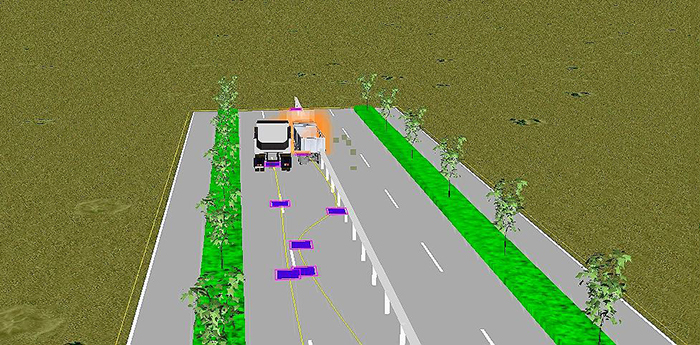
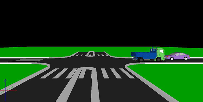
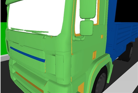
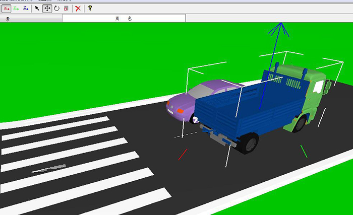
Click on the zoom tool in the toolbar, then drag the mouse up and down in the operation area, you can zoom in or down the screen, so as to view the screen from the whole to the part or from the part to the whole. Take the perspective as an example of enlargement, as shown in the following figure: after enlarging the picture, the truck head can be clearly observed.
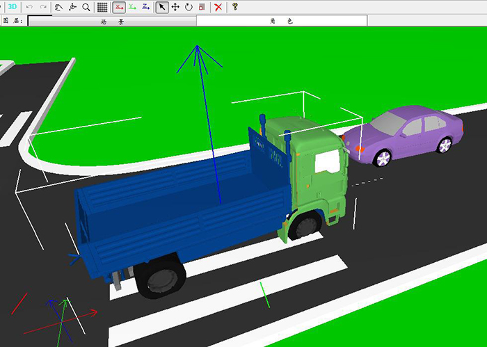

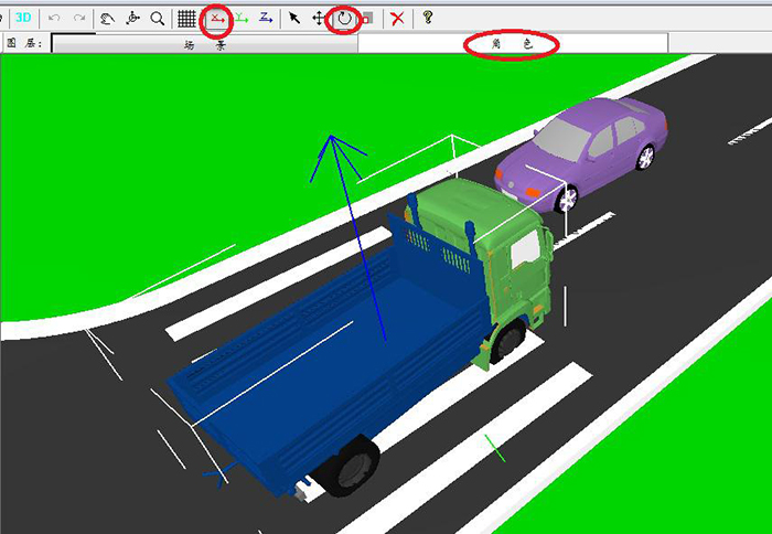
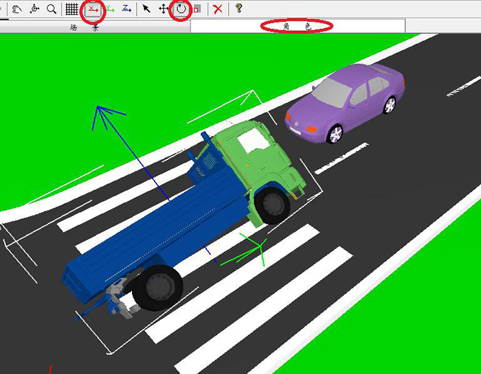
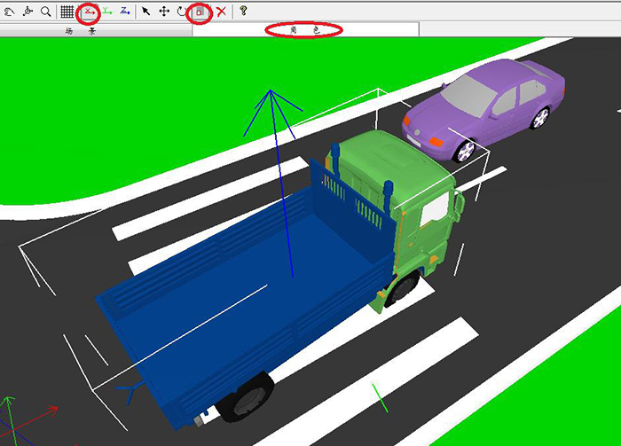
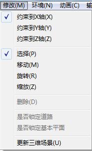
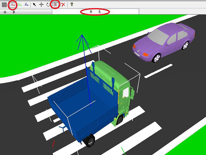
Select the "role" layer, then select the "X axis", then click on the "zoom" tool, click on the pre-zoom object, and move the mouse to zoom the object. As shown in the figure below, the truck shrank on the X-axis.
6. Adding and modifying roles and scenarios
1. Addition
(1) Adding roles
When adding roles, we need to select the role layer, switch the model bar to the role model automatically, select the pre-added role model category, pop up the thumbnail drop-down menu, and intuitively select the pre-added model. Take adding a "two-car" as an example, as shown in the following figure:

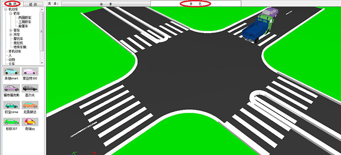
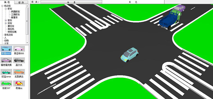
Select the "Role Layer". The left model bar automatically switches to the role model addition menu. Click on the "+" in front of the "Motor Vehicle". A drop-down menu appears. Similarly, click on "Car" and select "Car". The thumbnail will show different types of Cars. Select the pre-added objects and drag them to the operation area. You can add it. As shown in the following figure:
(2) Replacement roles
If two-dimensional files are imported and the imported roles do not conform to the reality, you can click on the roles, a drop-down menu appears, and select the appropriate roles in the menu.
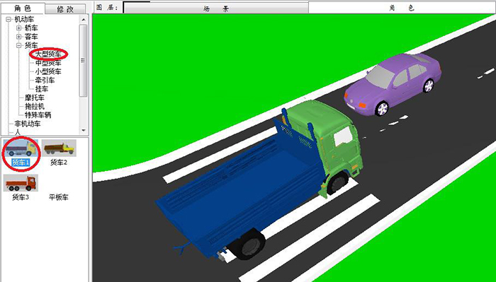
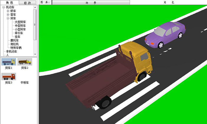
Take the replacement truck as an example, replace the original truck with a large truck, click on the "motor vehicle" and select the "large truck". A thumbnail of the large truck appears below. As shown in the following figure:
The role of the selected large truck can be replaced by dragging it to the original truck position. As shown in the following figure:
(3) Adding Scenarios
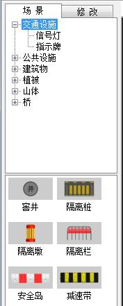
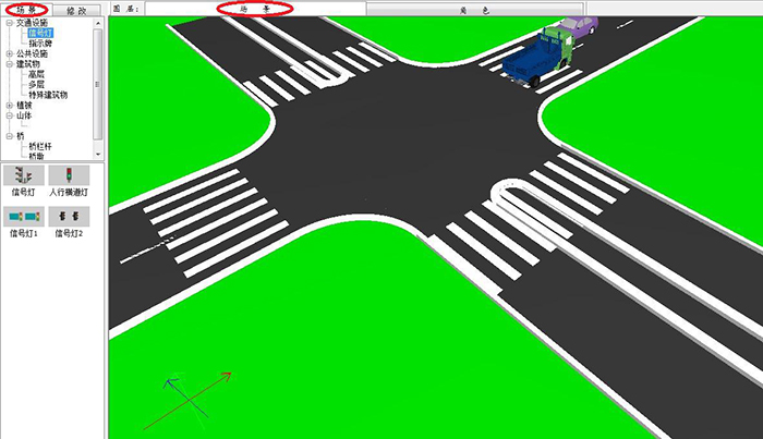
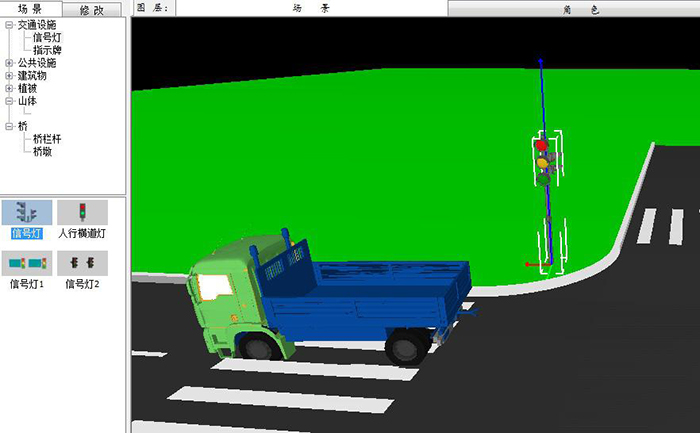
When adding scenes, we need to select the scene layer, switch the model bar to the scene model automatically, select the category of pre-added scene model, pop up the thumbnail drop-down menu, and intuitively select the pre-added model. Take adding a "signal lamp" as an example, as shown in the following figure:
Select "Scene Layer". The left model bar automatically switches to the Scene Model Addition Menu. Click on the "+" in front of "Traffic Facilities". A drop-down menu appears. Click on the "Signal Light" in the drop-down menu. Four types of signal lights will be displayed in the thumbnail. You can add them by selecting the pre-added object and dragging it to the operation area. 。 As shown in the following figure:
2. Modifying roles
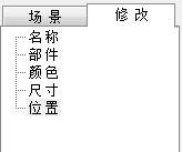
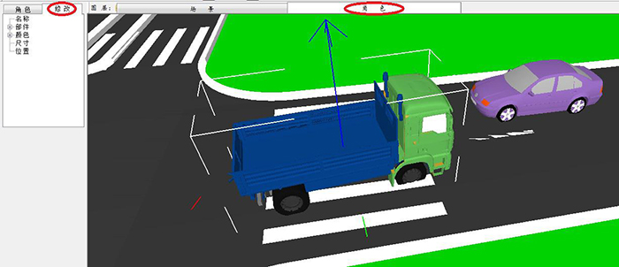
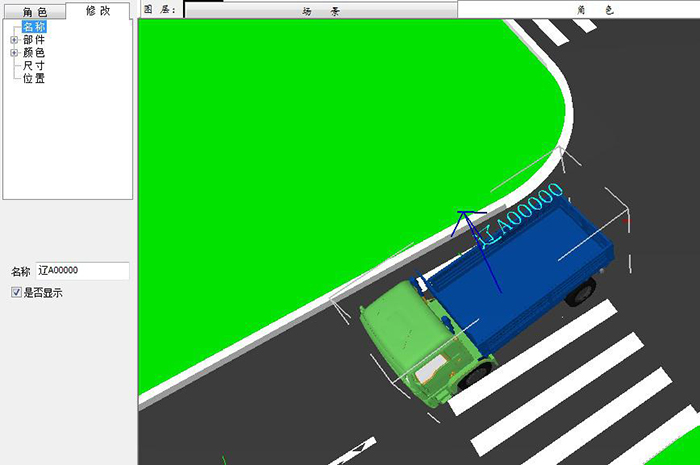
Click on the Pre-Modified Object in the Role Layer, and click on Modification in the Model Modification Bar on the left. Take the modification of trucks as an example, as shown in the following figure:
The drop-down menu of the modification bar shows: name, parts, color, size, location.
(1) Name modification
Click on "Name" and a modification dialog box appears below. You can enter the name of the pre-modification object in the dialog box. Click on "Show or not" to display the modified name above the object. As shown in the following figure:
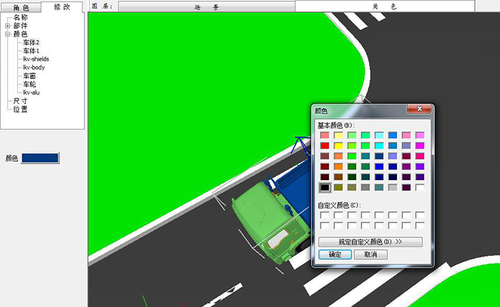
(2) Modify the color
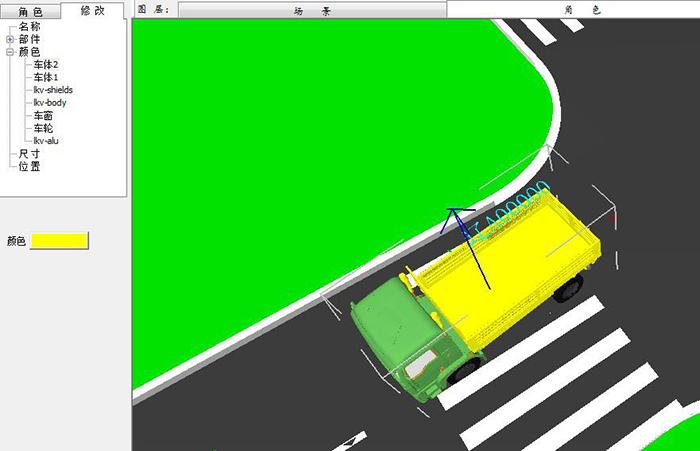
Click on the "color" to appear a drop-down menu to modify the color. It shows the name of the part where the object can modify the color. Select the name of the pre-modified part. The dialog box appears below. Click on the color dialog box to play the excellent version. You can choose the color in the color plate. Take the modification of the "body 2" color of a freight car as an example, as shown in the following figure:
Select yellow and click OK to generate the following image effect:
7. Bloodstains, Scatters, Traces
1. Introducing blood stains and scattered objects
Introduce a two-dimensional traffic accident scene drawing bloodstains and scattered objects, as shown in the following figure:
Click on the tool to generate a 3D effect, as shown in the following figure:

2. Import Traces
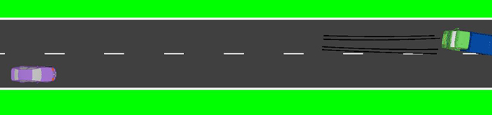
Import a two-dimensional traffic accident scene map with traces, as shown in the following figure:
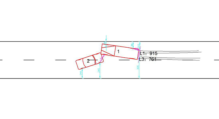
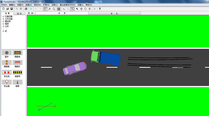
Click on the tool to generate a 3D effect, as shown in the following figure:
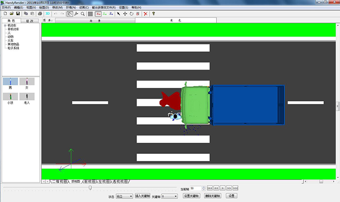
8. Generating Animation
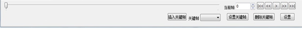
Animation editing area can be used to edit animation, insert, delete and set key frames, edit the animation process and time. As shown in the following figure:
Example 1: Car collision (flame effect)
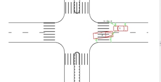
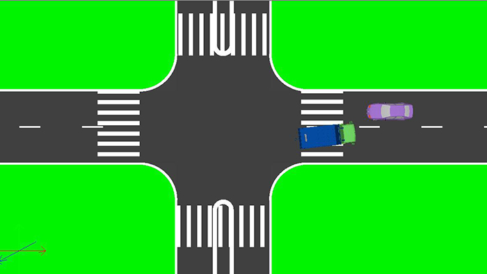
Taking the top view of the collision of two vehicles as an example, this paper introduces how to generate animation and how to make the flame effect.
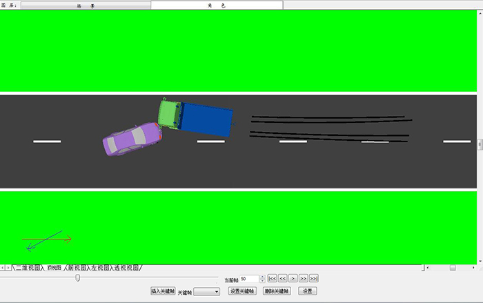
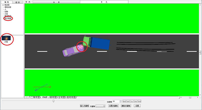
Step 1: Enter 50 in the current frame dialog box (i.e. set the current frame to 50th frame). Assuming that the 50th frame collides, click "Insert Key Frame", select "Particle System" in "Role Model Bar" in "Model Bar", and drag it to the position where the car collides. As shown in the following figure:
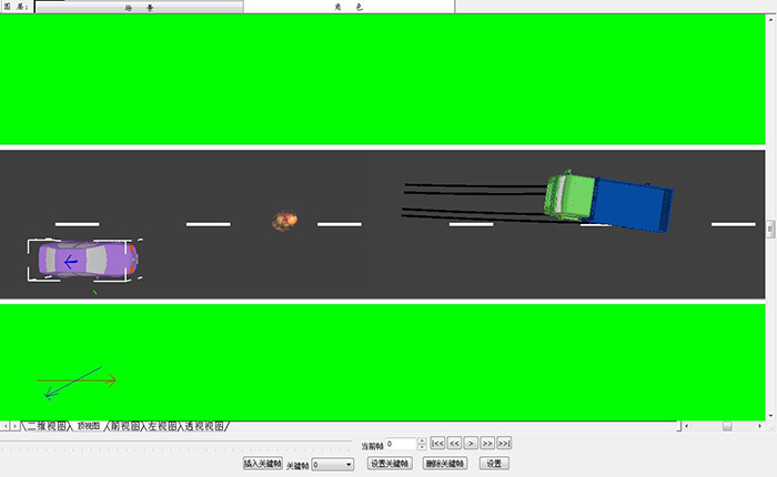
Step 2: Enter 0 in the current frame (that is, set the current frame to the starting frame), click "Insert the key frame" and then drag the two cars to the pre-collision state, as shown in the following figure:
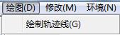
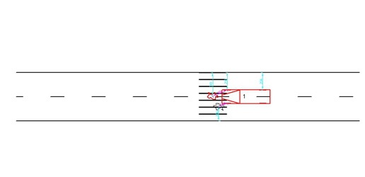
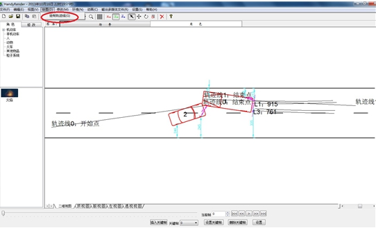
Step 3: Switch "Top View" to "Two-dimensional View", click "Drawing" in the menu bar, and then click "Drawing Trajectory Line" to draw the trajectory of car collision process, as shown in the following figure:
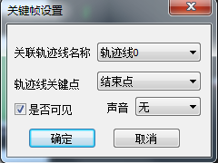
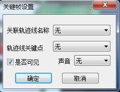
Step 4: Switch the "two-dimensional view" to the "top view", select the car, click the key frame button, and a dialog box appears, as shown in the following figure:
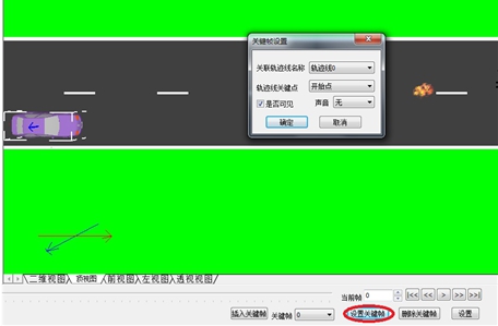
Step 5: In the name of the associated trajectory, select the name of the corresponding trajectory (trajectory 0); in the key point of the trajectory, select the "starting point"; select whether the car is visible (that is, whether the car is visible at the starting point), and then click to determine. Truck operation is the same as car operation.
Step 6: At the same time, select the flame at the 0 key frame. In the key frame setting dialog box, cancel whether it is visible (that is, no flame in the absence of traffic accidents). As shown in the following figure:
Step 7: Select the trace, and a dialog box will appear in the animation operation area.
The start frame is the time period when the trajectory begins to appear, and the end frame
That is to say, all the trajectories show the time period. As shown in the following figure:
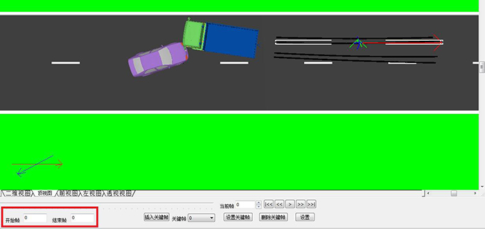
According to the example, the start frame is set to 20, the end frame is set to 50, and the input number is set to complete the production of this trace (each trace needs to be set).
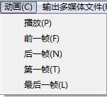
Step 8: This group of buttons, from left to right, are: start frame, previous frame, play, next frame, end frame. Click on the "Play" button to see the animation effect. You can also click the "Play" button in the front view, left view and perspective view to observe the animation in different traffic.
Example 2: Traffic accidents caused by collisions between people and cars (character animation)
Taking the top view of human-car collision as an example, this paper focuses on how to operate the character model in animation.
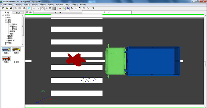
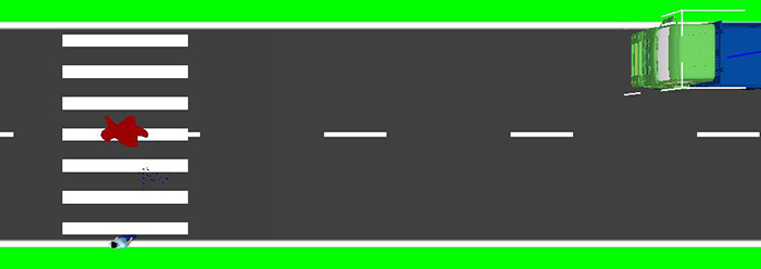
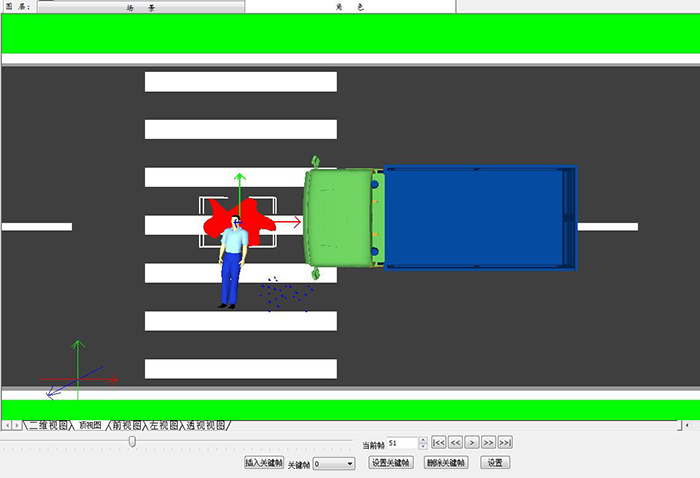
Step 1: Import a two-dimensional traffic accident scene map with trucks, bloodstains and scattered objects to generate 3D effects. As shown in the following figure:
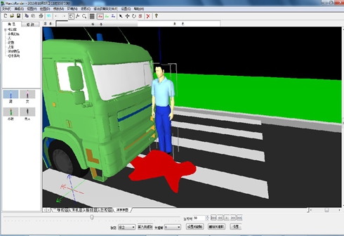
Step 2: Add the human body in the role layer, click on the role model library, select the human body, drag to the screen, take perspective as an example to see the added character model more clearly, as shown in the following figure:
Step 3: Switch "Top View" to "Two-dimensional View", click "Drawing" in the menu bar, and then click "Drawing Trajectory Line" to draw the trail line of the truck. As shown in the following figure: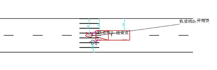
Step 4: Switch the view to the top view, and set the current frame to 50 (assuming that the frame collides in the 50th frame). Then click on the insert key frame to modify the location of the truck, the person, the bloodstain and the scattered object, respectively. When modifying the location of the truck, select the truck and click on the key frame. The dialog box appears as follows:
Name of associated trajectory: trajectory 0; key point of trajectory: end point; visibility: visibility, and then click to determine. As shown in the following figure:
Step 5: Go back to the top view, set the key frame to 0, and click Insert the key frame. Move the human body to the position before the impact; select the truck and click on the key frame, as shown in the following figure:
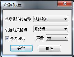
Name of associated trajectory: trajectory 0; key point of trajectory: starting point; visibility: visibility, and then click to determine. As shown in the following figure:
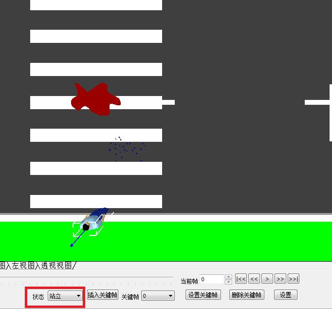
Step 6: Emphasize how to set human body, input 0 in the current frame, click on human body, insert key frame, character status: choose to stand. As shown in the following figure:
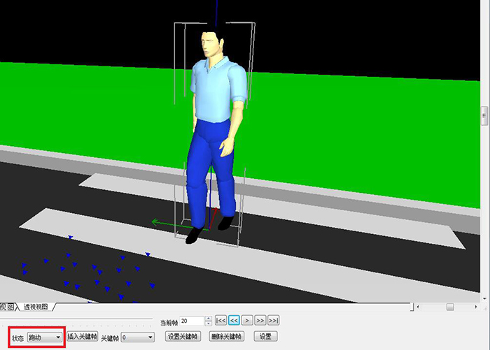
Current frame input 1, click on the human body, character status selection: run, insert the key frame. As shown in the following figure: (Running state can be clearly seen in perspective)
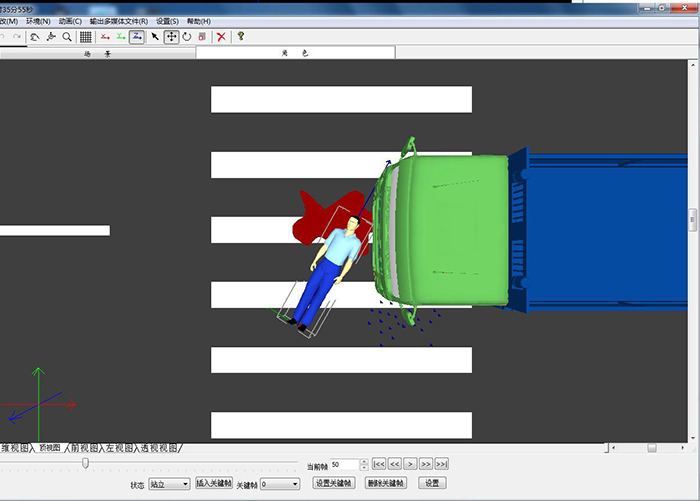
Step 7: Set the current frame to 51, that is, the human body state after impact, click on the human body, insert the key frame, and the human body state chooses to stand, and then adjust the human body to the state of the accident scene by means of rotating and moving tools combined with X, Y and Z axes. As shown in the following figure:
Human body description:
Standing state at frame 1 and 0, running state from frame 1 to frame 50, and falling state at frame 51, that is, the state of traffic accident scene map after traffic accident.
2. If there is an error in inserting key frames in the human body setting step, you can click the delete key frame button and insert the key frames from the new settings.
Step 8: Enter the current frame into 51, click on the bloodstain, insert the key frame, click on the settings of the key frame, pop-up window, as shown in the following figure:
When the selection is visible or not, Click to confirm the effect as shown in the following figure: blood stains appear after the impact.
Step 9: Input the current frame into 0, click on the bloodstain, insert the key frame, click on the settings of the key frame, pop-up window, as shown in the following figure:
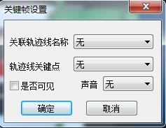
Whether the choice is invisible or not, Click To determine the effect as shown in the following figure: there is no blood on the ground before the impact.
The production of scattered objects is the same as blood stains.
Step 10: Click on the "Play" button to see the animation effect. You can also click the "Play" button in the front view, left view and perspective view to observe the animation in different traffic.
9. Output of Multimedia Files
If you click on the output multimedia file in the menu bar, a pop-up window will appear, as shown in the following figure:
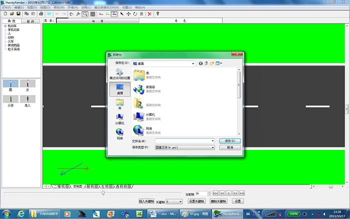
Enter the name of the file (e.g. traffic accident scene simulation), save the type in AVI format, click the save button, and a dialog box appears to select the video compression format, as shown in the following figure:
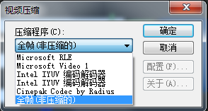
After choosing the compression format, the multimedia file can be output.