
Preface
According to the statistics of the Ministry of Public Security, in the first half of 2011, there were 1840998 road traffic accidents in China, an increase of 18502 cases over the same period of last year, with direct property losses of 440 million yuan. Indirect losses are even more incalculable. Traffic accidents are causing road congestion and disturbing people's travel every day. How to deal with traffic timely, accurately and quickly? The key to traffic accident scene disposal is to keep the road unblocked. At the same time, in the process of accident disposal, we should embody the guiding ideology of scientific and technological policing, use high-tech means to improve the efficiency of traffic accident scene disposal, and electronic management of traffic accident cases is also an urgent need of traffic police departments.
Traffic Accident Site Drawing System in the past can only draw by computer from the original drawing standards of paper and pen, which makes the drawing standardized and unified. However, the drawing process is cumbersome, and it does not solve the problem of on-site investigation and measurement, and can not improve the speed of dealing with accident scene by traffic police, thus increasing the intensity and complexity of the work of traffic police. It also requires a long training process in computer graphics.
"Photogrammetry System" also can not solve the problem of traffic accident scene investigation and survey, which is complicated in operation, weather-constrained, unable to use at night, unable to deal with large-scale traffic accident scene, can only carry out plane measurement, has large errors, and can not produce the detection report of measurement department, and the technical level of users. It's too demanding.
The Traffic Accident Scene Survey System developed by our company in 2013 has fundamentally solved the problems of traffic accident scene investigation and mapping. It can not only realize standardization, integration and electronic management, but also be free from weather, light, waterproof, shockproof, dust-proof, industrial product design and use environment. Low requirements; easy to use; first-time users will; do not need a long training process; just click the button, you can accurately measure and plot; so that the survey of traffic accident scene becomes accurate, fast, easy and convenient. Improve the efficiency of dealing with traffic accidents, quickly dismantle accident sites, avoid traffic congestion and relieve traffic pressure, thereby reducing social and economic losses.
2. The Framework of Traffic Accident Scene Survey System
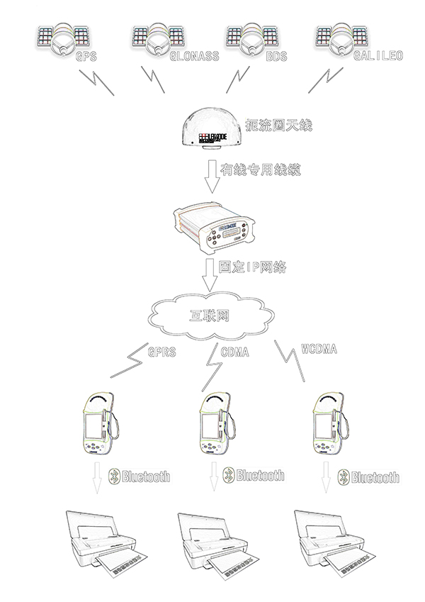
The traffic accident scene investigation system includes: traffic accident scene investigation instrument, traffic accident scene investigation server (including server, choke loop antenna).
Its working sketch is as follows:
Technical parameters
1. Choke Antenna
The choke-coil antenna can effectively suppress the effect of multipath effect, combine with the uncompromising stable phase center (less than 1MM) and suppress radio frequency interference. Low noise, low consumption, and synchronous frequency selection function.
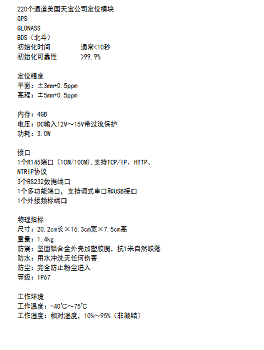
2. Server Technical Parameters
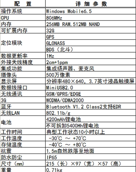
3. The technical parameters of the prospector are as follows:
4. Instructions for the Use of Explorators
This product has obtained the national patent, patent number: 201320688050.4
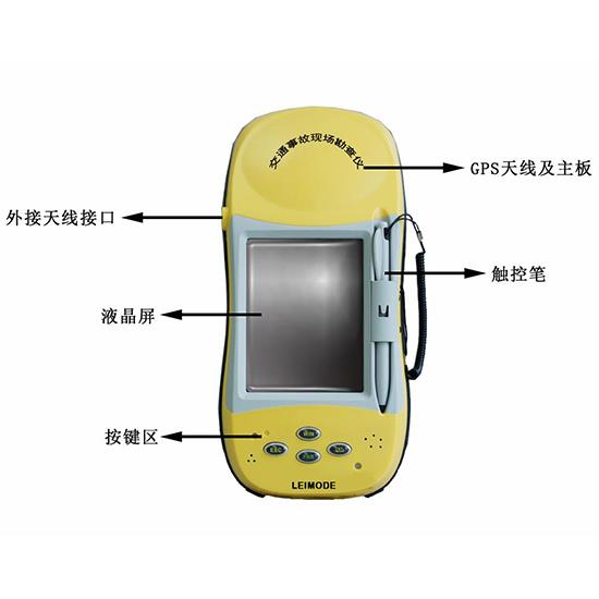
(1) Components and operation instructions of traffic accident scene surveyor
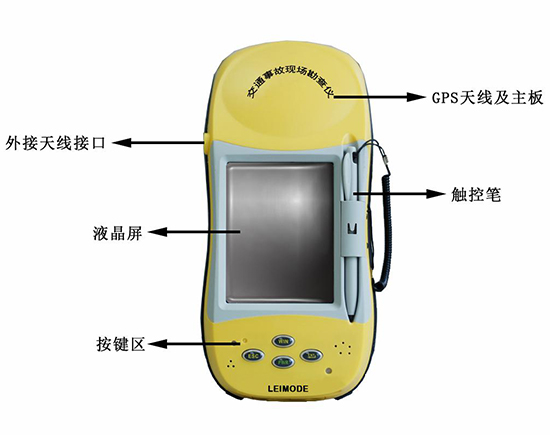
There are four buttons, two indicator lights and one restart key in the key area, namely: win key, ESC key, ent key and PWR key; two indicator lights are: working status indicator and power indicator; concave small button is the restart (reset) key, located in the upper left corner of the key area next to the indicator light.
1. Boot-up
(1) Hold down the PWR key for three seconds, and then turn on when the red light goes out and the blue light comes on.
(2) After booting, the screen will appear: Windows logo and Windows welcome interface.
(3) Note: If the reconnaissance instrument is in use and standby (just close the screen), press the PWR key, it will wake up the screen and the interface before it appears.
2. Shut down and restart
If you press the PWR key for 3 seconds, a prompt box will appear in the interface. If you click on the appropriate option, you can restart, shut down and cancel it, or you can click on it directly with a touch pen, and the prospector will restart.
3. How to Use the Touch Pen Correctly
(1) The stylus is located in the front groove of the prospecting instrument, and the stylus is gently pulled out from the end of the pen cap.
(2) When the touch pen is put in, the pen cap goes out and press gently until the top of the pen cap is equal to the surface of the prospecting instrument.
(3) Attention: Do not exert too much force when taking out and putting in.
4. Installation and disassembly of SIM cards
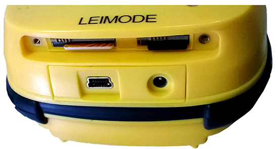
Installation of SIM Card
(1) Remove the bottom cover of the main engine with a screwdriver. There is a slot at the bottom, and the slot on the left is the installation slot of the SIM card.
(2) Push the metal contact of the SIM card upward and the notch to the right, and insert the SIM card lightly.
(3) If the SIM card does not pop up after release, the SIM card will be installed.
5. Dismantling SIM Card
Simply press the SIM card, you can pop up.
Installation and disassembly of storage cards
Install memory card
(1) The bottom chuck of the prospector and the slightly smaller chuck on the right are the storage chute.
(2) Push the metal contact of the memory card upward, the gap to the left, and insert the memory card lightly.
(3) If the memory card does not pop up after release, it will be installed.
Remove the memory card
Press the memory card lightly and it will pop up if you release your hand.
6. How to Charge and Use Lithium Batteries Correctly
(1) In order to prevent data loss during battery extraction, the prospector uses a built-in 4200 MH large capacity lithium battery, which can provide the prospector to work normally for more than 10 hours.
(2) Batteries are not charged when they are out of the factory. Therefore, before using them, it is necessary to charge them until at least five charging and discharging processes are completed before the maximum capacity of the battery can be achieved.
(3) Lithium-ion batteries must be charged before use. The charging time is 4-6 hours. The charger has the function of charging and protecting.
(4) Important tips: In order to prolong the battery life, charge the battery lightly when the temperature is 0-45 degrees. 50% charging instruction is useful for fast charging, which can be filled in only one hour.
(5) Connect the charger, when the host red light is on, it means charging is in progress, and when the red light is off, it means charging is completed.
7. How to Use and Keep Exploration Instruments Correctly
When using the prospecting instrument, please use it strictly according to the operation manual. For the first time, the power of the prospecting instrument should be used up and charged for more than 8 hours. If the prospector is not used for a long time, please charge the prospector. Store the prospector in a cool and dry place. Batteries need to be charged every other time to prevent the battery from completely running out and affecting its life.
(2) Surveying the scene of road traffic accidents
1. Start on-site investigation of traffic accidents
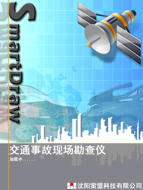
After the probe is turned on, click on the Smart Draw icon on the touch screen. The screen shows the start-up interface of road traffic accident scene investigation, as shown in the following figure (left). After that, it will automatically enter the traffic accident scene investigation guide, as shown in the following (right) chart:
In the right picture, click the "OK" button at the top corner, which means that the current operation steps are completed and the next step can be performed.
2. Procedures for scene investigation of traffic accidents
In the following exploration and acquisition steps, all the symbols and roads follow the three principles of red, yellow and green. Red means: initial state, yellow means: selected state, green means: acquisition completed state.
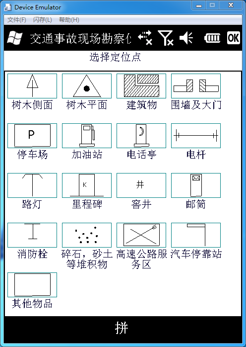
(1) Selection and acquisition of locating points
When the traffic accident scene investigation guide is opened, no operation judgment is needed. The survey instrument will automatically guide the exploration steps. First, the screen shows the following picture:
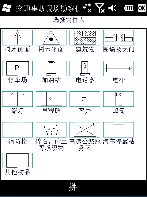
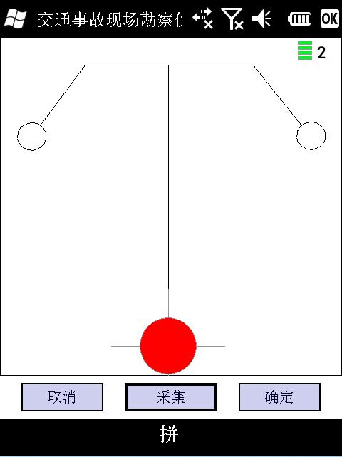
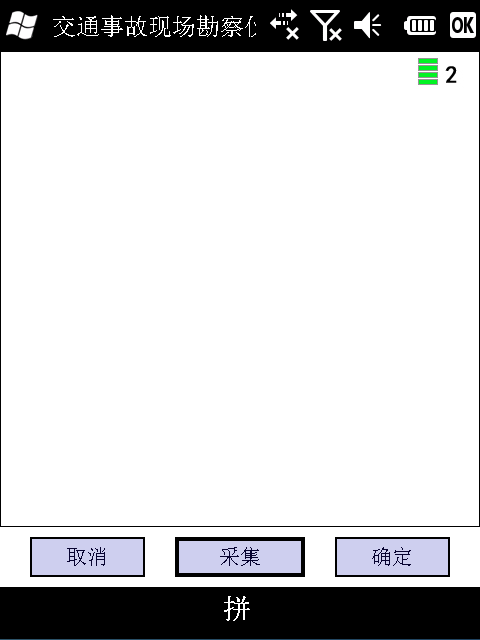
Select the location point to be collected directly by clicking on the touch pen. Take the street lamp as an example. The touch pen clicks on the street lamp icon. The screen shows as follows:
Touch pen clicks on the red dot under the street lamp, the red dot becomes red to indicate that it can be collected. Workers go to the street lamp and close the top of the prospector to the street lamp (the closer the top of the prospector is to the pre-collection point, the more accurate the location of the collection) press the "ENT" key (or click "collection" with the touch pen), and the successful collection is yellow. When the display turns green, the acquisition is completed, and the touch pen clicks "OK" to enter the next exploration link.
(2) Selection and acquisition of locating lines
After collecting the locating points, the screen will automatically guide to the next step, select and collect the locating lines, as shown in the following figure:
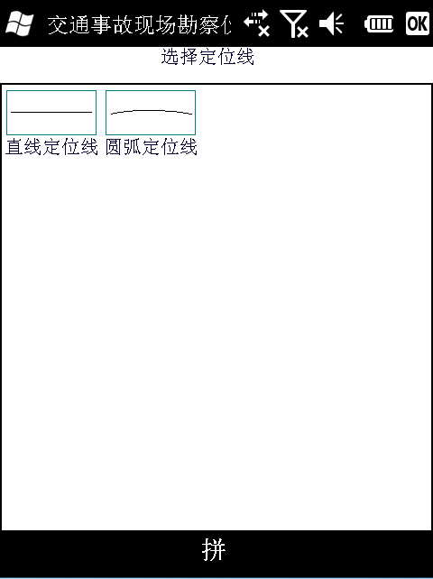
The locating lines are "straight line locating line" and "arc locating line", while the touch pen clicks "straight line locating line" as shown in the following figure (left); the touch pen clicks "arc locating line" as shown in the following figure (right):
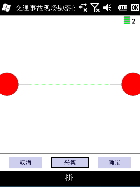
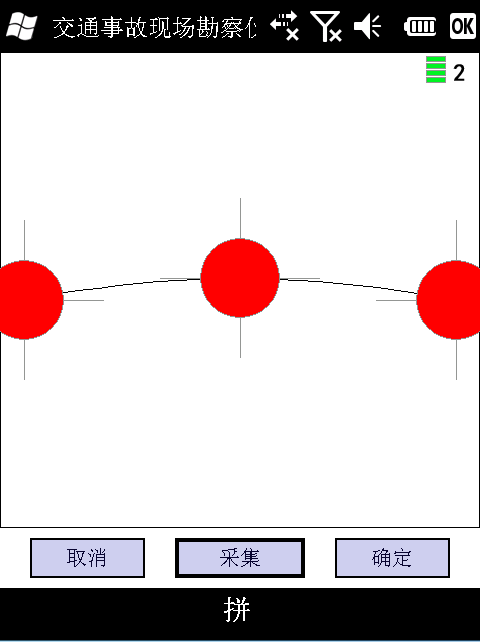
Taking the selection of "straight line positioning line" as an example, the touch pen clicks on any red dot (before and after the position part) and the red dot clicked turns yellow. This means that it can be collected. The staff go to the position of the pre-collection positioning line, press the "ENT" key (or click "collection" with the touch pen), and the yellow dot turns green. The second red dot is also collected.
After the acquisition, the touch pen clicks "OK" and enters the next exploration stage.
(3) Selection and collection of vehicle symbols
After collecting the positioning line, the screen will automatically guide to the next link, select and collect the fixed icons, as shown in the following figure:
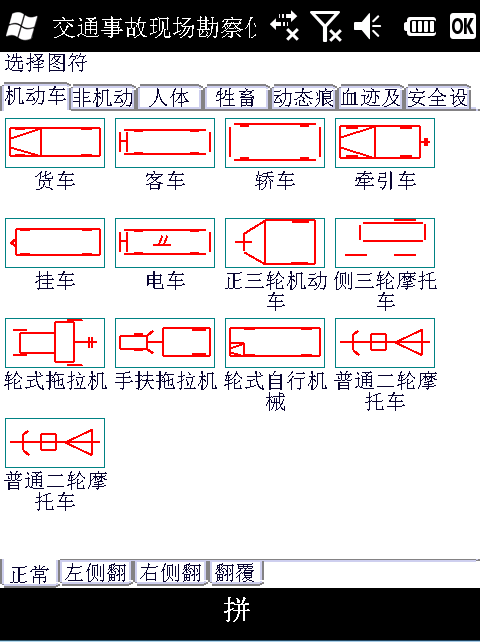
The library is divided into eight categories: motor vehicle, non-motor vehicle, human body, livestock, dynamic traces, blood traces, safety facilities. Click on the menu of each category to show the thumbnails in the categories below.
Under the thumbnail, there are four options: normal, left-turn, right-turn and overturn, which correspond to different shapes of icons respectively.
Take the choice of "car" as an example, as shown in the following figure:
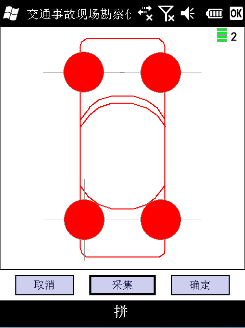
The screen shows the car plane charts, the top is the front end of the car, and the bottom is the rear. Four red dots appear on the car charts. Two points can be selected arbitrarily as the acquisition points. The acquisition method is the same as the acquisition of the positioning point and the positioning line. After the collection, click "OK" and enter the next exploration link.
Collection of non-motor vehicles, human bodies, livestock, etc.
(4) Selection and collection of traces
After collecting the vehicle and other icons, click "Dynamic Trace" in the paging bar of the operation area. The screen is shown as follows:
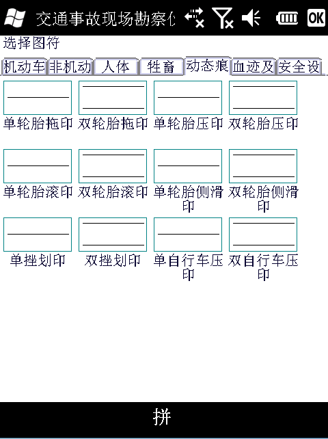
Select the trace type in the preview box. The screen is as follows:
If the trace is a straight line, the trace can be generated by clicking "collection" and "determination" at the beginning and end of the straight line trace respectively.
(2) If the traces are curves, the traces can be generated by clicking on "collection" and "determination" at the starting point, inflection point and end point of the traces respectively.
(5) Drawing and Generating Paths
In the operation of drawing and generating roads, the stylus clicks on the road, that is, the selected road, and the stylus clicks on the blank area for more than one second, that is, the initial operation state.
The acquisition mode is the same as that of locating points and locating lines.
(1) Drawing roads
After collecting the locating points, locating lines and icons, click the "OK" button and enter the link of drawing the road. The screen is shown as follows:
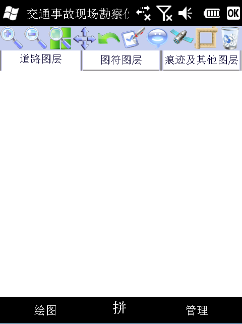
The screen operation area is divided into three layers: Road Layer, Symbol Layer, Trace and Other Layers.
Select the road layer and click the "Drawing" button below the screen in the "Road Layer" operation area below the commonly used toolbar, as shown in the following figure:
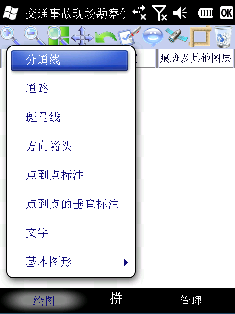
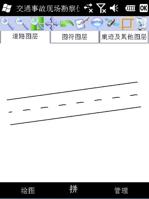
Select the "road" and gently pull it on the screen with a stylus to draw the road, as shown in the following figure:
(2) Revising the Road
A. After drawing the road, we need to modify some basic road information, such as the dividing line, zebra line and so on. Take modifying the dividing line as an example, you can click the "Drawing" button under the screen and select the "dividing line" in the menu, as shown in the following figure:
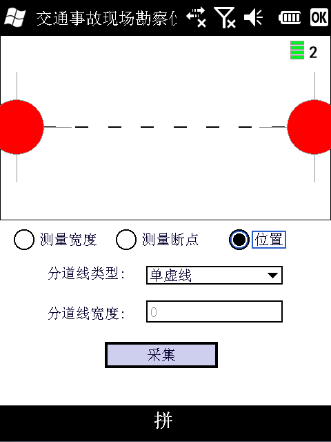
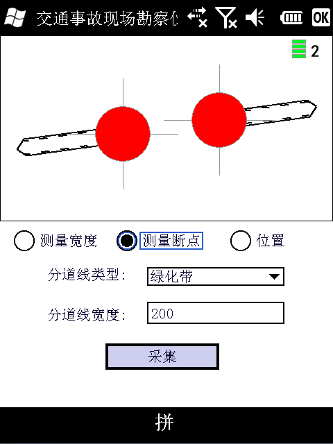
B. Take "green belt" as an example in the type of dividing line. The operation is as follows.
By interrupting the green belt and choosing to measure the power failure, the distance between the two breakpoints can be collected, as shown in the following figure:
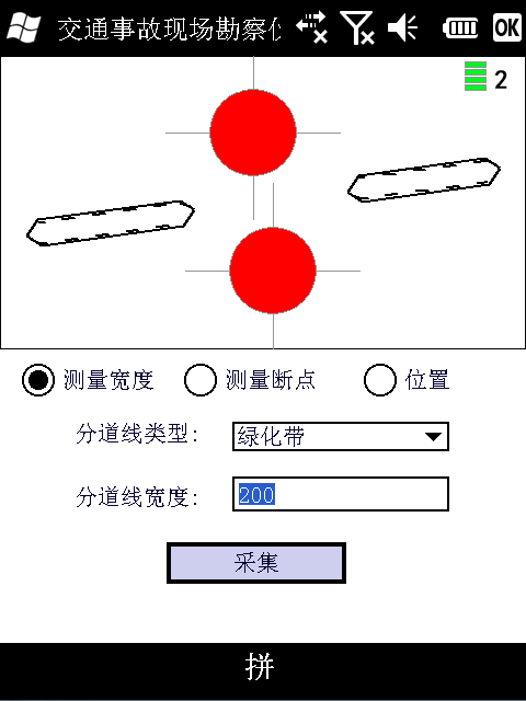
C. The width of acquisition greening bandwidth can be acquired by choosing "measuring width", as shown in the following figure:
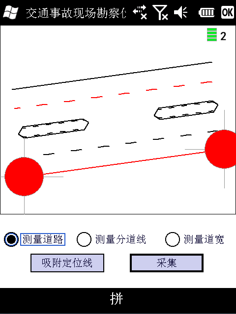
D. The roadside first absorbs the positioning line, chooses any line in the road which is close to the positioning line, clicks the "adsorption positioning line" button, the road can automatically absorb to the positioning line, as shown in the following figure:
(3) Drawing Basic Graphics
Basic graphics has an extension button, click "Basic graphics", as shown in the following figure:
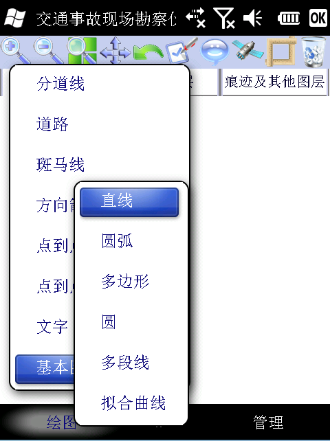
Basic graphics include drawing: straight line, arc, polygon, circle, multi-segment line, fitting curve.
(3) Printing
1. Print the scale map of road traffic accident scene
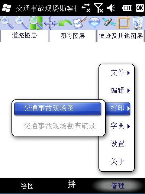
After all the exploration steps have been completed, click the "Management" button at the bottom right of the screen, as shown in the following figure (left); click "Print" to pop up the expansion menu, as shown in the following figure (right):

Select "Traffic Accident Scene Map" and the screen shows the following picture (left) to fill in the print information in the dialog box. Under the screen, a gray bar "Print" button appears, and a print preview window appears on the screen, as shown in the following picture (right):

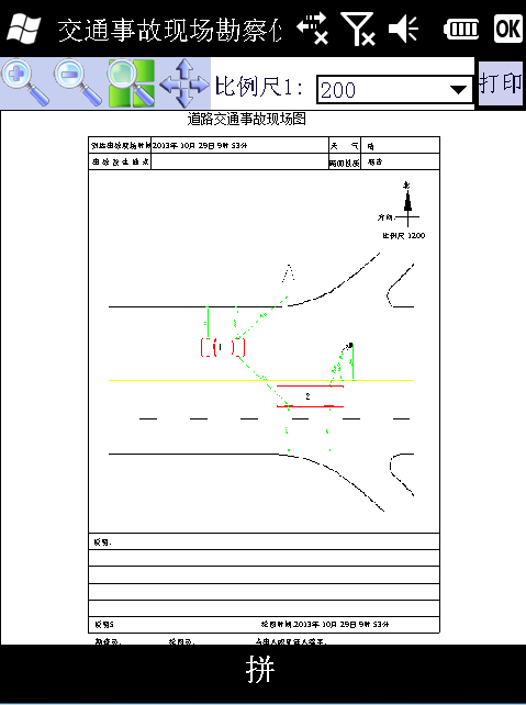
(1) In the print preview window, you can choose the scale size of the preprint scene map, as shown in the figure.
(2) In the print preview window, the touch pen clicks on the blank area outside the picture to enlarge, shrink, full-screen and translation the entire screen; the touch pen clicks on the scale area to enlarge, shrink, full-screen and translation the field map.
(3) On the top right of the screen, click the "Print" button to print.
2. The same is true for printing the record of traffic accident scene investigation.