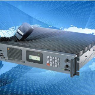
One KG510 The relay station consists mainly of the following units:
(1) Receiving unit
(2) Launch unit
(3) Amplifier unit
(4) Logical unit
(5) Control unit
(6) Interface unit (25-core expansion, 9-core write-out)
Note: KG510 Power Supply plus 13V is externally available.
Second, the working principle
(1) The principle of the receiving unit:
When the antenna signal is received, the available signal is selected by the 1STBPF band pass-through waver, amplified by the Q101 high frequency tube, and then the second stage 2ndBPF band pass filter selects the signal to 2ndMIX, the vibration frequency is provided by the RXVCO unit, but the RXVCO frequency changes high or lower, Control by the PIL IC101 phase ring, as the baseline frequency of the phase-locking ring is controlled by 12.00MHz crystals, and if the frequency of RXVCO changes, the PLL IC101 is controlled by the Q108 Q107 Q110 to control the change in RXVCO frequency. The frequency accuracy of pressure control is determined by crystal accuracy.
The first mixing from the RF amplification signal and the first vibration from the phase-locking ring synthesizer circuit each produce synth 48.5MHZ of the first medium frequency signal, after Q103 amplification, and then through two crystal filters to eliminate the channel's clutter signal, to IC106, TK10487 and the second vibration signal remix ingested a 44 frequency 50KHZ second MEDIUM FREQUENCY SIGNAL, THROUGH A NARROW WIDE CONTROLLER FOR 450KHZ CERAMIC FILTER SELECTION, AMPLIFIED BY IC106 OUTPUT IC107 TO THE LOGIC UNIT IC3AK2344 PROCESSING, PROCESSING SENT TO THE FRONT PANEL CONTROL UNIT FOR AUDIO AMPLIFICATION AND SENT TO THE SPEAKER.
(ii) How the launch unit works
First of all by the TXVCO unit to produce a carrier frequency, its frequency stability is also controlled by the phase-locking circuit PLLIC205, its modulation is the use of dual modulation circuit working principle, this dual modulation phase phase synthesizer is generally produced with high precision and high-stability crystals, in order to achieve the phase-lock output frequency and crystal-like performance , this system can be used for direct FM, as analog modulation or digital modulation, the general phase modulation circuit only modulated VCO, and the dual modulation method is modulated VCO, and modulated crystal reference source, through mutual compensation to achieve arbitrary low-frequency modulation frequency bias. MAX DEVI ADJ is used for modulation frequency bias amplitude normal value 3.5KC-4KC modulation on the TXVXO unit after Q215 pre-amplification and then after the last stage Q216 amplification sent to the amplifier, the output power 250MW, one has TX output, At the same time, a DC control voltage is sent to the amplifier unit via the CN201 port.
(iii), the function of the amplifier unit:
The signal sent from the transmit to the amplifier front RA07A4452 module is amplified, and then received amplification by Q504 (power can be adjustable from 1W-50W).
The amplifier unit is mainly composed of the front-end amplifier, the wireless slot and the detection control circuit. The match between the front and the amplifier is to adjust the match by input fine-tuning capacitor FVC501, the adjustment of the amplifier and antenna slot is to adjust the match by the output capacitor FV505, there are no two positive reverse detection circuits on the main transmission line, D1 as a reverse power detection, once out of harmony, the reflection and the main wave ratio become smaller, so that the power becomes smaller, Controlled by IC502 and sent to the alarm circuit IC501 circuit. D2 is a forward detection circuit that detects the forward ratio by adjusting the front power through IC501, IC502. MAXPOW is to adjust the size of power, it is best not to mistune, because it has a impedance problem, and there is a power detection along the way, through the control sent to the panel to show the power strength.
(4) How the logical unit works
It is mainly composed of CPU, audio processor, memory, write frequency, alarm, working mode control, resty and other circuits, these circuits are related to CPU programs, what you want to do, are controlled by the front panel.
The composition of the panel
(I) Panel composition
Mainly by the panel keyboard keys, LCD display, audio output, horn headphones, power switch, microphone, power size adjustment, volume adjustment, rest adjustment are done in the panel, pay attention to all adjustments, preferably in the panel operation. The device inside the machine in addition to receiving the unit slot 6 screwcans can be adjusted, the rest do not move.
(ii), panel key operation
(1) Channel Conversion CH-Digital Key
(2) Conversion of relay and duplex shift-MON
(3) Power size conversion shift plus 2
(4) Read the current information shift 7
(5) Keyboard lock on or off shift plus 8
(6) Turn on or off programming scan mode shift-SCAN
(7) Press the MON key (when sub-audio is received, it can still be listened to)
(8) When SCAN is pressed, all are scanned
(9) Key transformation want to be next to the high channel CH-A
(10) Key transformation wants to be next to the low channel CH-B
(11) Hi is a high-power adjustment written in the software
(12) LO is the bottom power adjustment written in the software (Note: write low power, both holes can be adjusted)